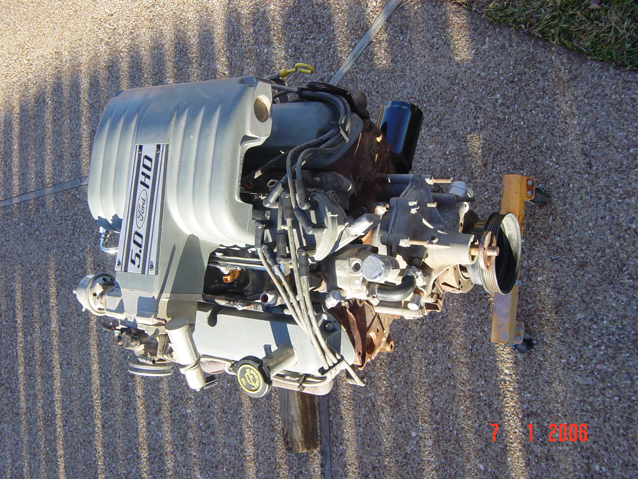
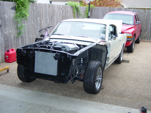
| In
order for a later model 5.0 to fit in an early
Mustang, either the oil pan needs to be changed or the
car's cross bracing/steering must be modified. I
chose the simpler and changed the motor's lower end
setup. Note the different in Early (64-72) and Late (79-95) Oil
pans. The rear sump of the late model interferes
with the cross member and steering. Required are a
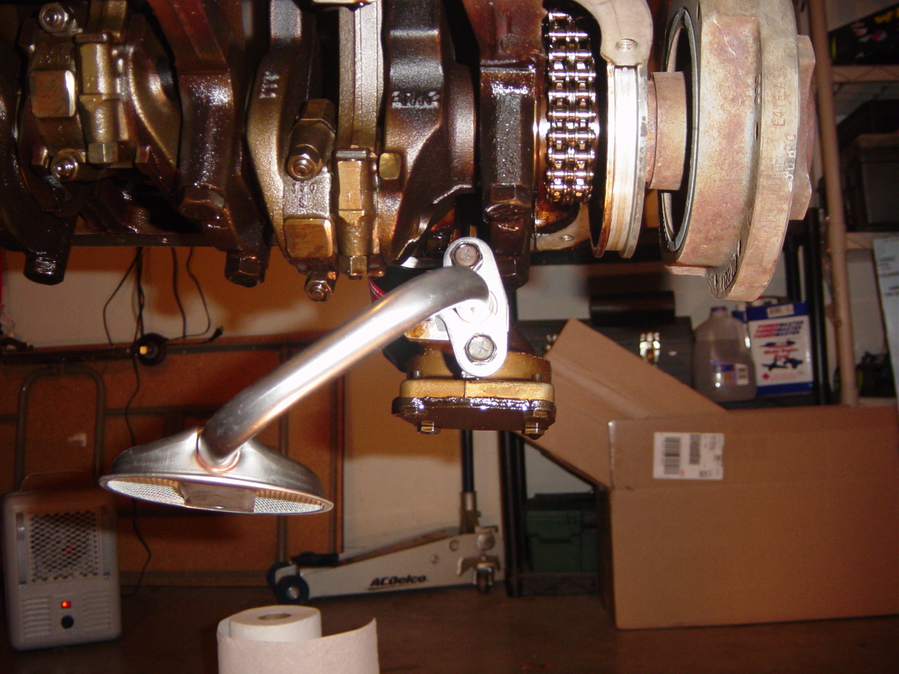
replacement SBF 260-289-302 oil pan (Ebay for <$35),
and a new oil pump pickup tube/screen (Melling brand
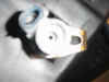
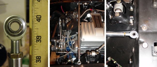
pickup tube/screen is <$10 @ Autozone). The Oil Pump Pickup photo
below shows the Melling unit installed and ready for the
new pan.
While you're in there, you'll need to relocate
your oil dipstick from the side of the block to the
front timing chain cover. First remove the old
dipstick and discard. I used a wooden dowel to
seal off the old hole. After the pan was
installed, I tapped the wooden down in the hole and
left it. The dowel absorbs hot oil and seals off
the hole.
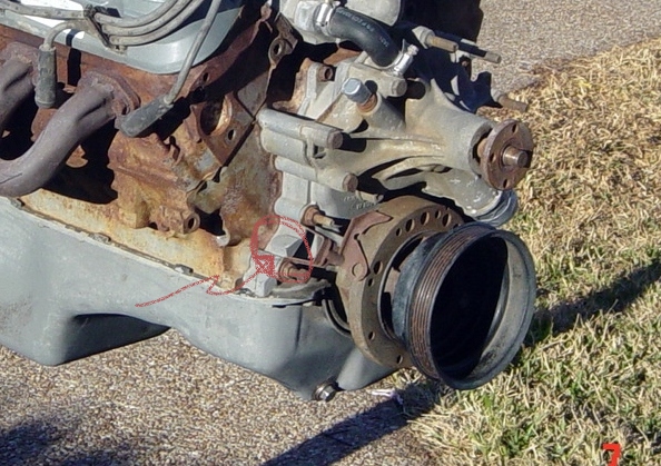
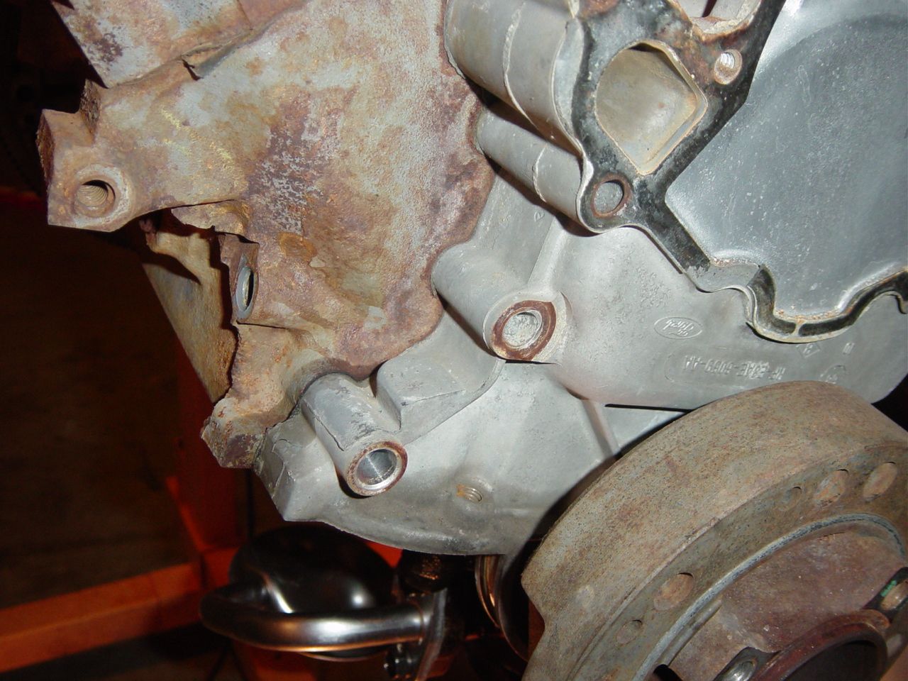
The dipstick must be relocated to the front of
the motor (Dipstick Location 1 below). This can
be done on or off the motor. Photos 2 and 3
below show where the boss exists in the cover. A
drill bit sized to the oil dipstick diameter is used
to drill out the boss and the oil pan
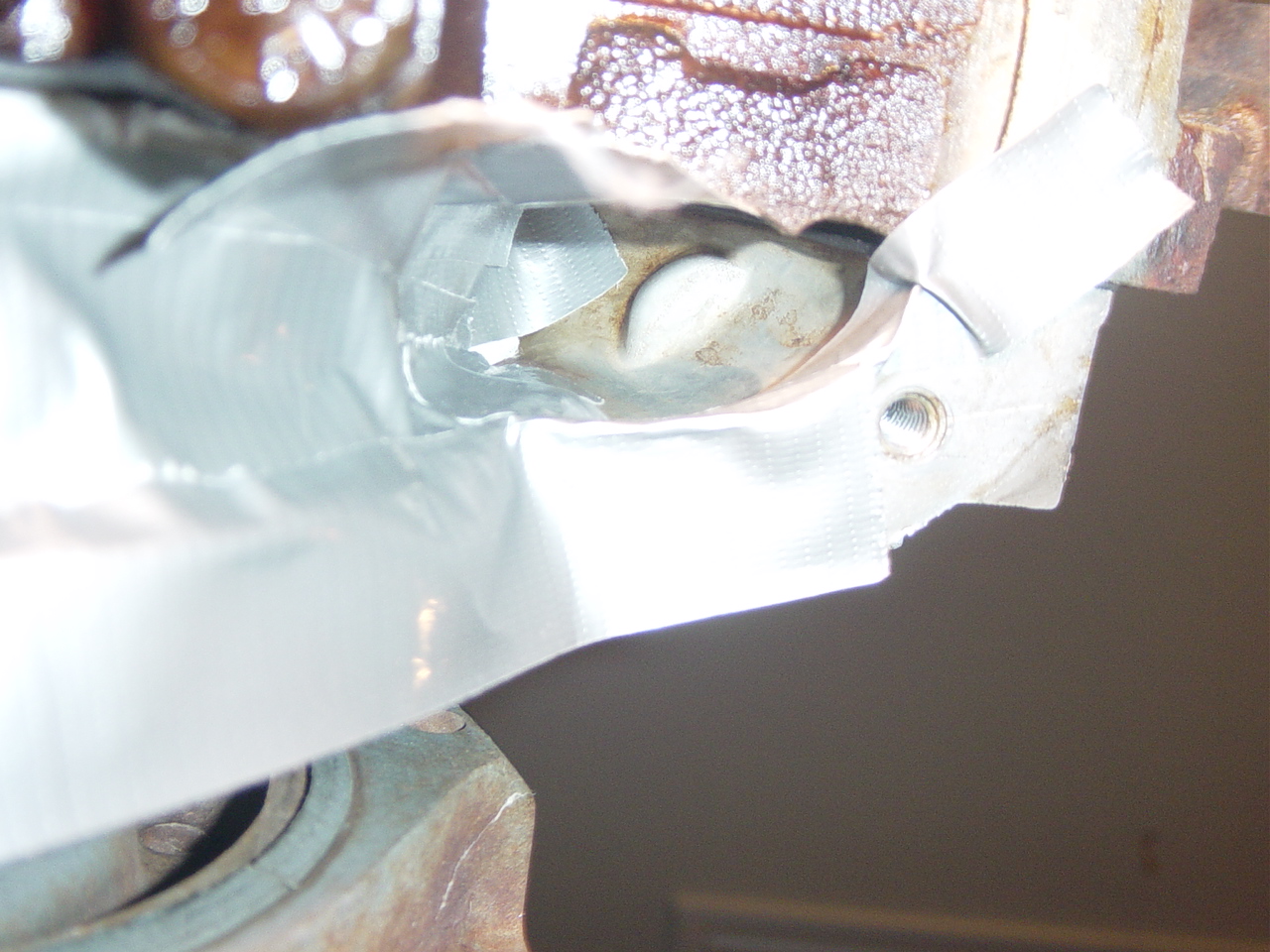
compartment. While I had the pan off, I cleaned
this corner of the pan/block with solvent, then masked
it off to ensure no shavings could migrate into the
lower end. (Pretty gutsy eh?) The motor bottom end was
taped off completely. After first drilling a
1/4" pilot hole, I stepped up to the correct diameter
bit. Care must be taken to ensure you establish
the correct angle so the dipstick tube can extend up
between the alternator and the head. Photo 4 below
shows the completed dipstick installation.
 |
 |
 |
 |
 |
 |
| Oil Pump Pickup |
Dipstick
Relocation 1 |
Dipstick
Relocation 2 |
Dipstick
Relocation 3 |
Dipstick
Relocation 4 |
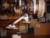
Early Model Oil
Pan |
Recommend spending the extra few dollars and
buy the high quality 1 piece Felpro oil pan
gasket. This is a steel cored synthetic rubber
coated unit. You DON'T want your oil pan
leaking. When installing your new oil pan, make
sure your mating surfaces are perfectly clean, and the
gasket is clean. Use the plastic ears that come
with the gasket to hold it in place while
installing. Tip: SBFs tend to leak oil at the 4
corners where the tabs of the gasket slip into the slots around the fwd
& aft crankshaft journals. Use a
little RTV to seal off these corners.
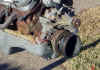
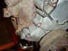
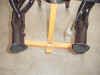
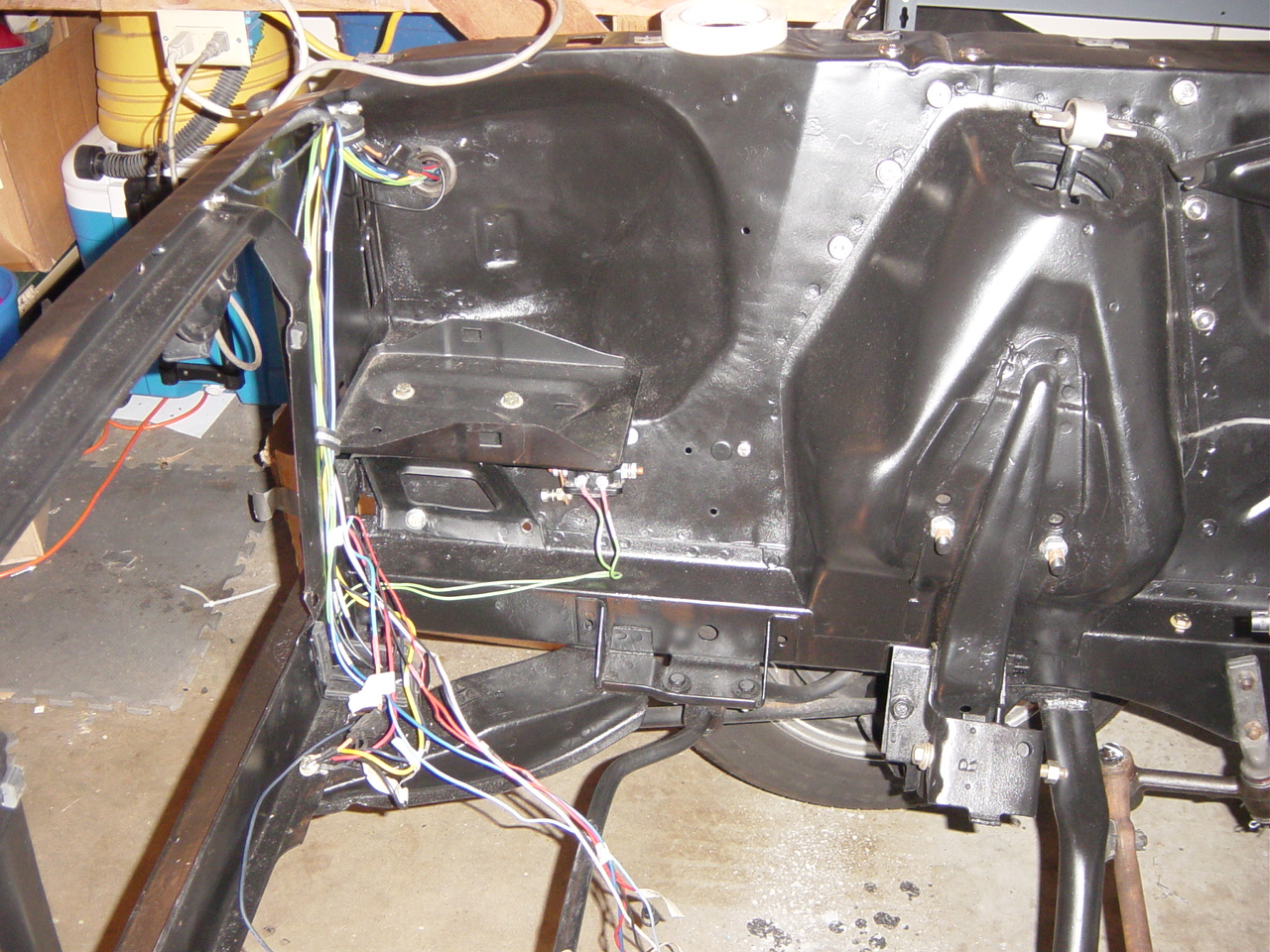
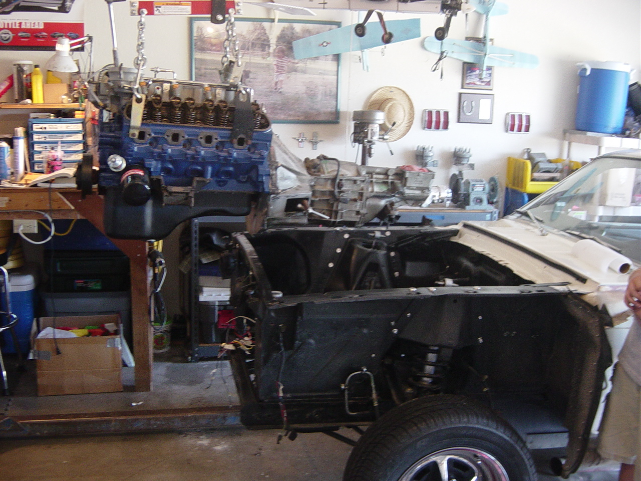
| Motor mounts: The two photos
(right) show the two pieces of a 1966 motor
mount. The lower unit is bolted to the
shock tower frame, and the upper unit is secured
to the mounting holes on the side of the
block. When the motor is dropped into
place, a single bolt (shown in the first photo)
is inserted through the side which pins the
lower between the two sides of the upper. This
makes for a very easy installation. |


|
 |
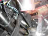
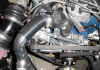
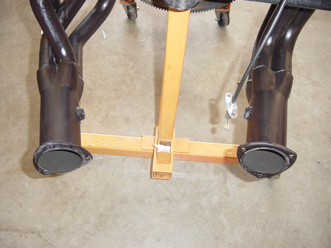
Headers/Exhaust/O2 Plumbing: The EEC requires HEGO (Heated Exhaust
Gas Oxygen) sensors to be mounted in the
exhaust system. These sensors monitor
the oxygen content of the exhaust and signal
the EEC as to the 'leanness' or 'richness' of
the exhaust. Threaded "Bungs" must be
welded into the exhaust system to screw
in the sensors. When stock early
model manifolds are used, the O2 sensor needs
to be welded into the exhaust pipe near the
attach point to the manifold. Late model
stock manifolds do not fit the early model
engine bay. I used Steve Ainsworth's (Ultrastang)
method of using 18mm spark plug anti-fouler as
the bungs to weld into my Hedman long tube
headers..
Instructions |
|
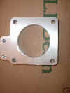
| Removal of EGR: Since I had removed all the smog items
from the 5.0, I also did not install
the EGR assembly (between the upper intake
and the throttle body). The EGR system is
designed to recycle burnt gasses
back into the intake for better emissions, and
an engine coolant circuit is used to cool the
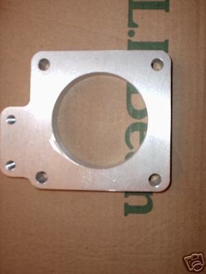
intake. I removed the EGR
assembly from the end of the upper intake and
removed the threaded rods. I purchased a
1/2" billet aluminum spacer place, which
functions to block off the upper intake and also
to provide mounting points for the throttle
linkage bracket. This plate (right) was
purchased off Ebay for approx $20, and can be
found in various widths. I chose the 1/2"
width because I needed something as short as
possible in order to use the factory rubber MAF
snorkel.
Along with removing
the EGR assembly, the coolant lines must be
removed, and the two coolant ports
plugged. the rear intake port can use a
standard threaded plug. The forward line
attaches to the 3/8" port on the upper coolant
tube. I filled the port with high temp
RTV, and then installed a small rubber plug on
top and secured with a hose clamp. An
alternative is to braze shut.
The removal of the
EGR requires a "dummy signal" to fool the EEC
into thinking it is still in place. A EGR eliminator
plug can be purchased from
FordFuelInjection for approx $20, and will
complete the circuit and keep error codes from
being produced.
|
|
|
Throttle Linkage: The
factory 5.0 Mustang throttle linkage is a good
choice for the early model transplant. The
factory linkage is long enough to reach from the
throttle body on the passenger side (left photo)
to the proper location on the firewall over the
gas pedal (right photo). Note: Because the
EGR spacer was removed, the throttle body is
moved effectively 1.5" inboard. The
throttle attach bracket will not mount to the
billet spacer because it interferes with the
coolant tubes. The throttle attach bracket
must be modified to clear the obstructions. For a gas pedal, I used a standard 1970
pedal, and modified the upper end to reach the
throttle cable. |
|
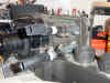
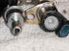
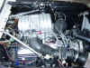
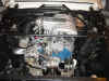
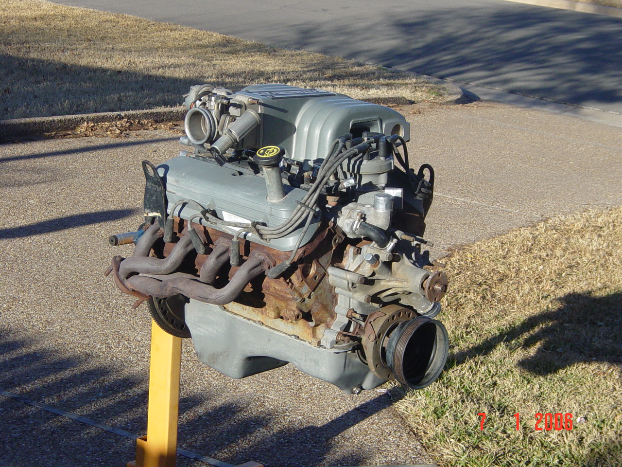
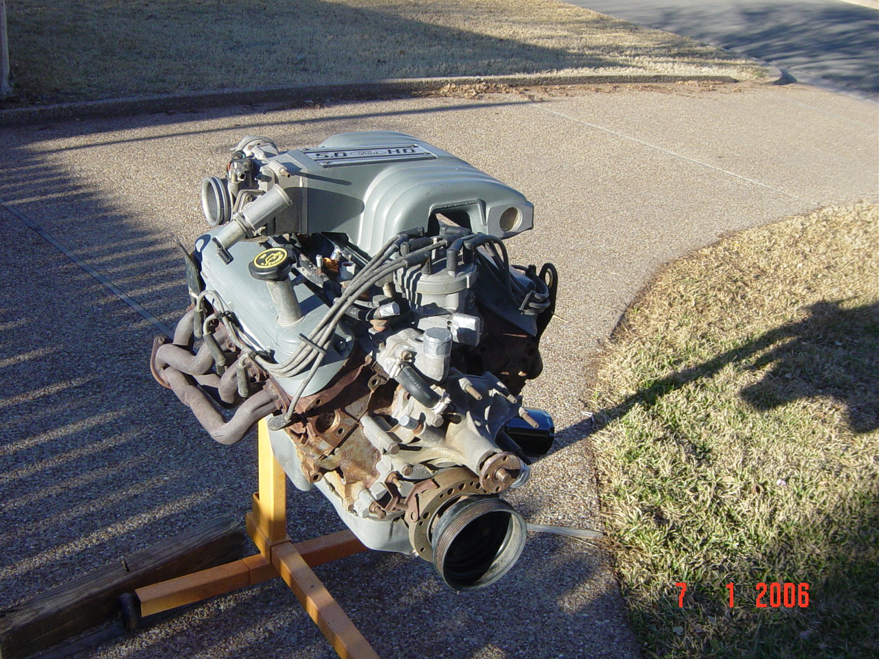
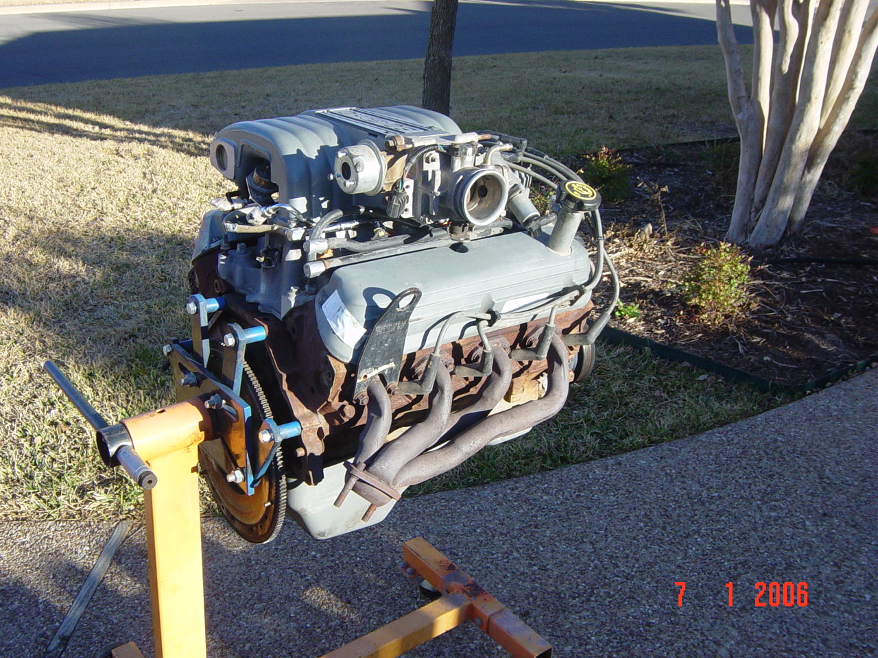
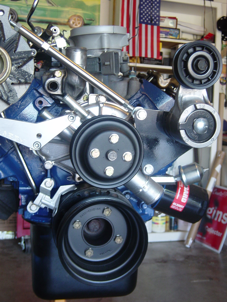
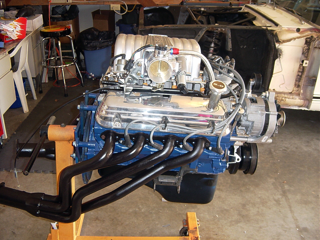
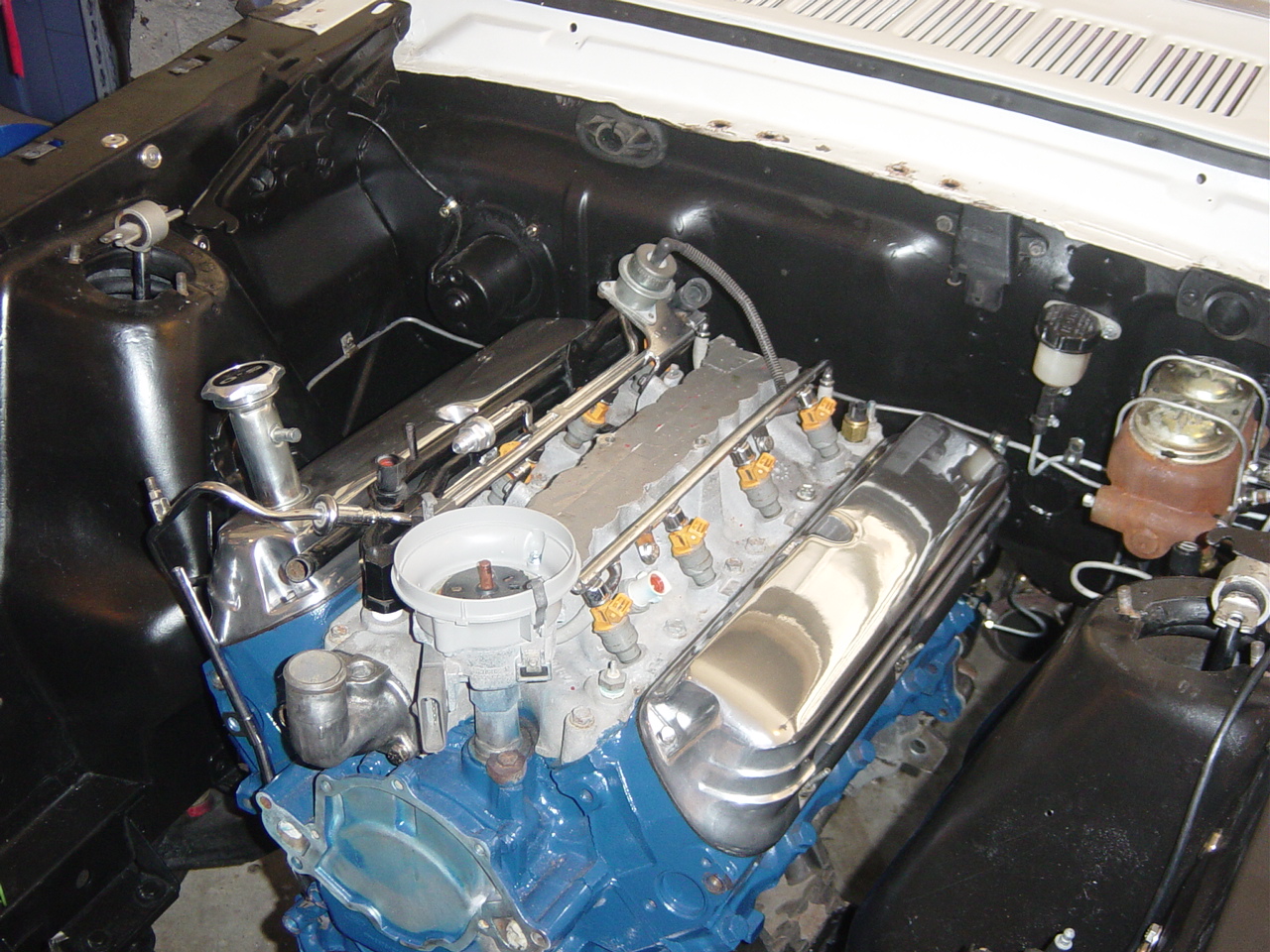
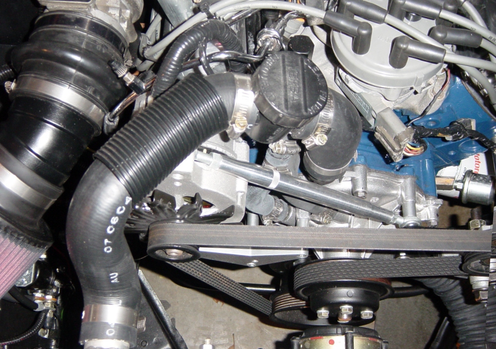
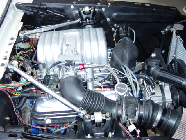
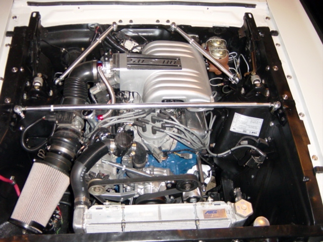
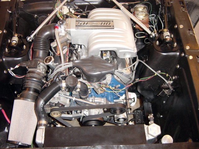
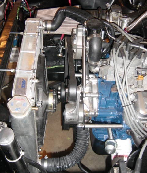
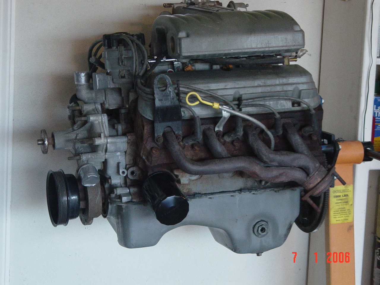
| Serpentine Belt Mount: Note in the photos of the donor motor
above, there were no accessories. Kind of
a blank slate. There are SO many
choices regarding belts depending on what you
currently have, and what options your car
contains. Since I did not have A/C or PS,
I was left with the typical Alt-Crank-Water pump
triangle. Then the question becomes,
standard or reverse rotation water pump and V vs
Serp belt. Changing to a V belt would have
meant getting another harmonic balancer that was
correct weight with a 3 bolt pattern. It
also would have meant changing to a different
timing cover and a standard rotation water
pump. Too much cost. In the end, I
chose to leave the timing chain cover and
reverse rotation water pump as is, and run a OEM
serpentine path minus the AC, Smog, and P/S.
These missing items required the addition of an
alternator mount, and an idler pulley
mount. I chose a
March alternator mount and a
Trick Flow Idler pulley mount. March
makes both, but the Trick Flow is about 25%
cheaper. (But the March would have
matched). By using the TF
bracket, the idler pulley moves over to replace
the A/C and P/S pulleys in the circuit. I also installed a high volume polished
water pump. The belt is a Goodyear Gatorback; I
believe 59". Also, you will
need to get another Idler pulley that is
grooved. Check Summit for best
pricing on the brackets. |
|
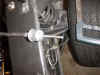
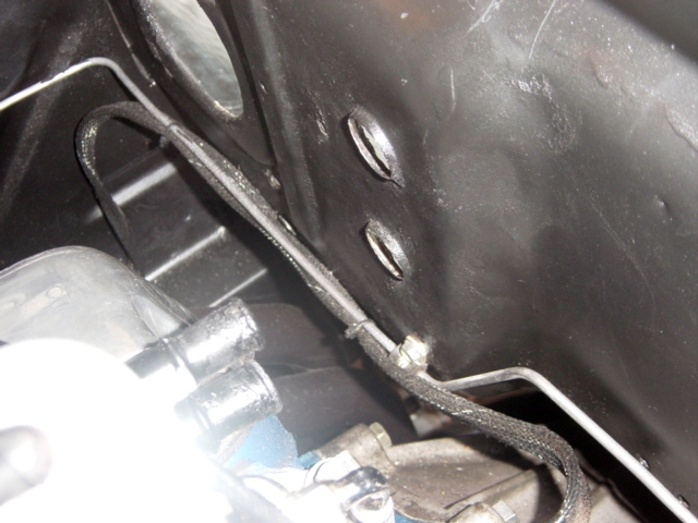
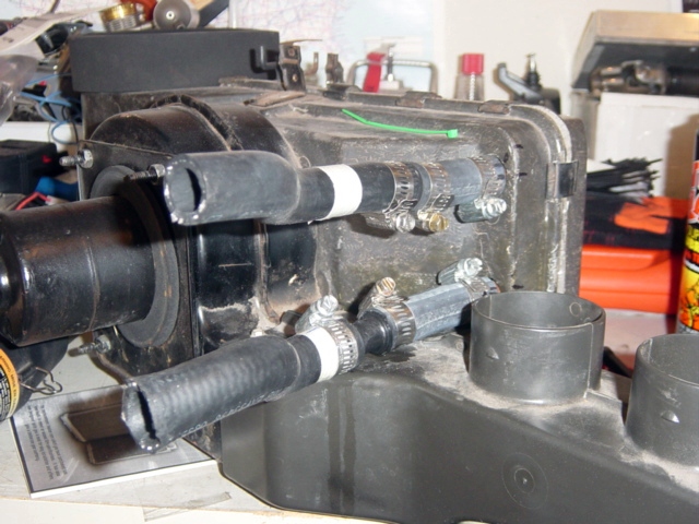
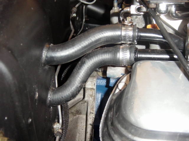
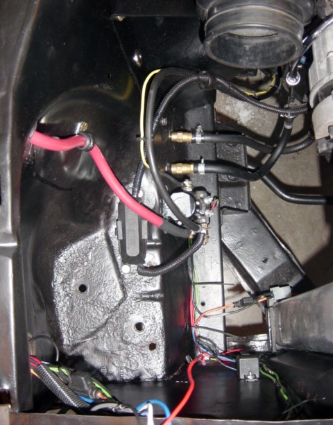
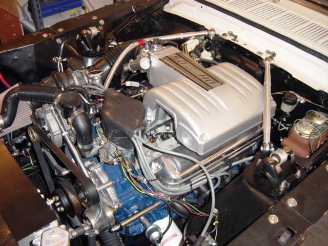
Heater Hoses
|
Heater Hose
Routing: The donor 5.0 motor has the
standard metal heater tubes which run the length
of the pax side of the intake. This is a
much neater looking system than the old heater
hoses. To attach, I chose to use
pre-formed heater tubing to attach these lines
to the existing heater core, as well as clean up
the appearance of the installation. In the
top left photo, note the close positioning of
the tubes to the firewall. I took the area
measurements and headed to the local autoparts
store to cruise through the hose racks, looking
for suitable bends. After several tries I found
two hoses that had bends within them that fit
the situations. I took these, and cut out
the useable bends, and attached to the heater
tubes. This left a portion extending
inside the firewall. To connect to the
heater core, I used straight hose, with a
straight line coupling. (lower left
photo). In the end, the installation fit
very nicely. (Click photo at right for a
larger view). When choosing donor hoses
for their bends, choose carefully. The
formed hoses are expensive and the autoparts
store will not take them back once you've cut
them up. Update: Per Corky: Use a Gates
20662pn 90d 3/4-5/8 hose on the lower(3/4)
tube, then use a Gates 28625 90d 5/8x5/8 hose
connector to splice/connect the lower heater
hose coming from the firewall. The upper
heater hose can be used with no splice.
What a time & headache saver!! |

|
|
|
Radiator Hoses: Once again, installations will vary based
on the size/type of radiator and the upper
intake location. I have an AFCO aluminum radiator
installed, which moves the upper hose
location further to the passenger
side. I also use an in-line Tefba
filter to keep debris out of the
radiator. To mate the motor and
radiator, I used a standard Mustang 5.0
upper radiator hose, and spliced in the filter
at the most optimum point. Had I not had
the inline filter, I would have still used the
stock hose, but cut and inserted a piece of
steel tubing to adjust the distance. The
lower radiator hose outlet on my radiator is on
the driver's side (same as water pump). I
used a standard flex hose to fit. While
not as visually pleasing as the pre-formed
hoses, the universals come with a steel spring
which keeps them from choking down during a
strong coolant vacuum. |
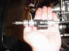
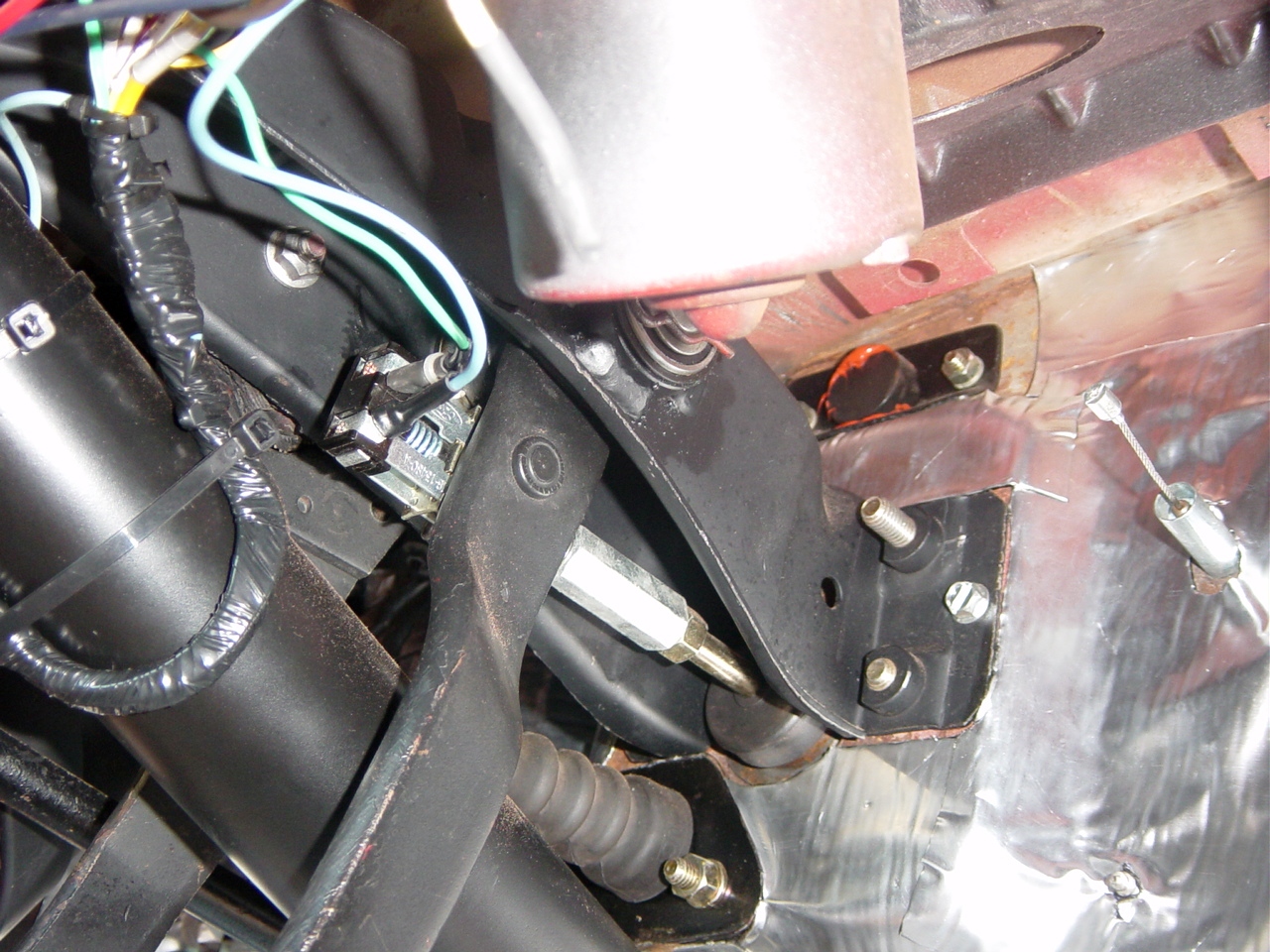
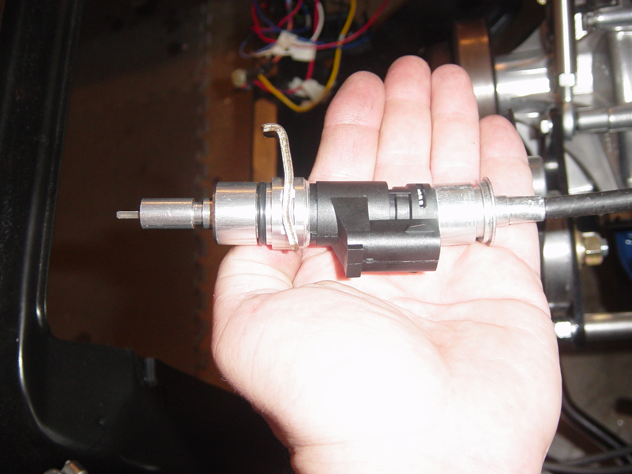
| Speedometer Cable Modification: In order
for the EEC to sense a deceleration condition, it has to be connected to the
transmission. Pins 3 and 6 of the EEC are
connected to the VSS, or Vehicle Speed
Sensor. This sensor is mounted to the
transmission end of the speedo cable. (See
photos right). To mount the VSS, remove
the plastic speedometer gear from the end of the
cable and cut off the end of the housing.
Some people cut off a portion and drill up the
end of the VSS to fit. I removed the total
end of the cable housing, leaving the end of the
speedomer cable. then I drilled a small hole in
the end of the VSS. This allowed me to
insert the end of the cable into the end of the
sensor to engage the internal mechanisms.
The to pieces are secured together using RTV and
a hose clamp. Lower right photo shows the
assembled parts. The plastic speedometer
gear is then reinstalled onto the end of the VSS
sensor. Note: If I was to get a 'do over',
I would leave approx 1/4" of the gear shaft, and
updrill the size of the interior housing to
mate. This would make for a more secure
alignment. Note…on an automatic
transmission, installation of VSS, is only
needed to prevent a code
Another option for
those who don't like cutting up there
speedometer cable is to purchase a completed
assembly from Ron Morris.
|
|
|
 |
|
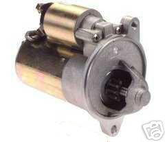
Accessories:
Starter:
Best to use the late model starter.
These PMGR "Mini-Starters" are very powerful,
very efficient, are smaller, lighter, and are
not prone to heat soak. It has ample
clearance from the long tube headers.
Installing a mini-starter requires modifying
the starter wiring.
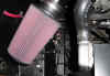
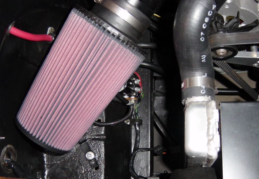
K&N Air
Filter: Another nice option is
using a universal conical K&N filter (P/N
RE-0920). I have not oiled it yet, don't
want it clogging the MAF sensor.
|
|
|
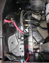
Alternator
Wiring: Photos
at the left represent the 2G Alternator
installation. The alternator is a standard
2G 75 Amp unit. I am not worried about the
need for extreme power, as I am not running any
overly power hungry accessories. If I had
a large stereo, I'd want to install the
3G..
Diagrams of
connections, schematics, and connector views
are shown here.
The wiring is fairly straight forward.
In addition to using these schematics, I am
using a Ron Morris alternator
pigtail. It is a very high quality
product. I did however, end up modifying
the Ron Morris harness to this schematic.
In the near left
photo, you can see the alternator cable, the
175A Megafuse, and the connections to the
starter solenoid. The output side of the
solenoid now is connected to and fires the
solenoid mounted on the top of the starter.
|
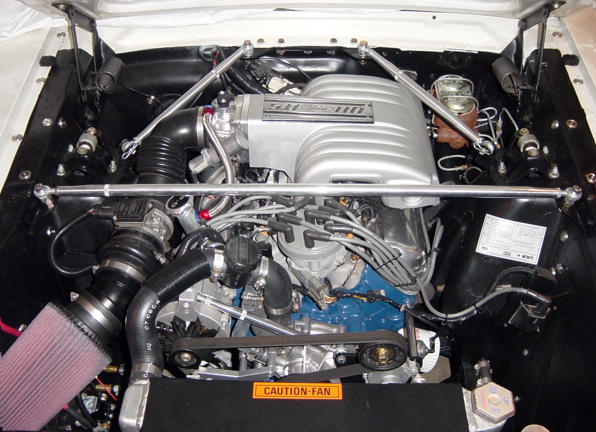
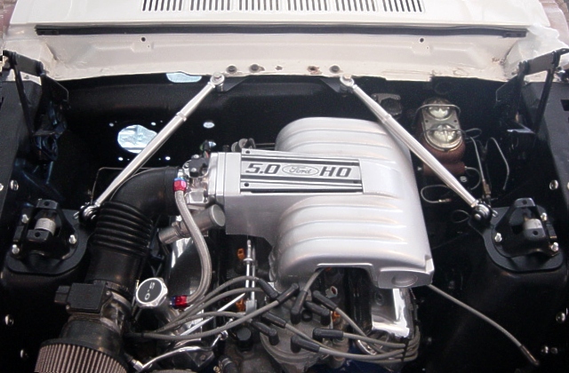
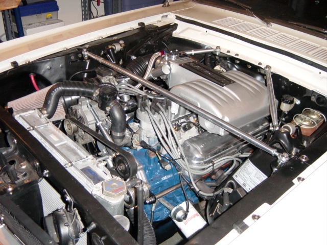
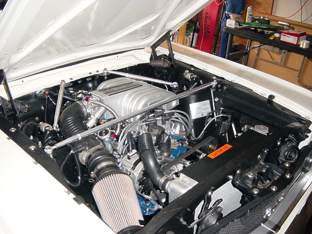
| Export Brace and Monte Carlo
Bar: The
upper intake of the 5.0 will not clear the
standard bracing of a 1st generation
Mustang. The aftermarket export braces
will also interfere. There are several
options on the market, but I chose to build my
own as shown right. Detailed build
information can be found
here.
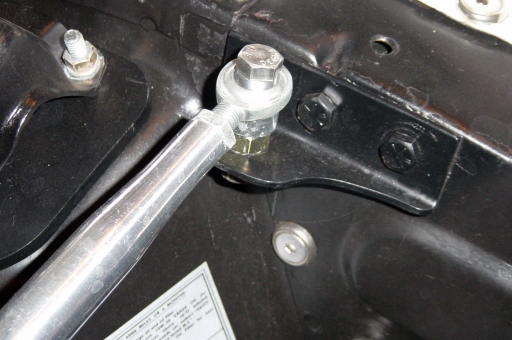
Detailed photos of
the custom Monte Carlo Bar are shown below.
|

|
| Reference Webpages: The
following webpages are good references and
support the details of the installation:
|
|
|


