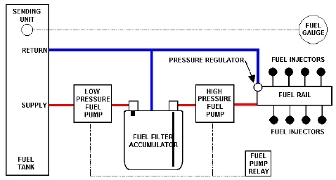
Pressurized Fuel System - EFI of a 65-66 Mustang Fastback
Before starting to install a high pressure, 2 line system in a mustang, the Ford Fuel Injection article written by Ryan McCormick Inject Your Horse - is a must read. This is the article from which my installation was modeled. I used (for the most part) the same components, and it worked perfectly the first time and has continued to do well.
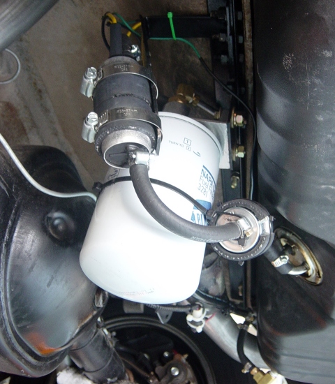
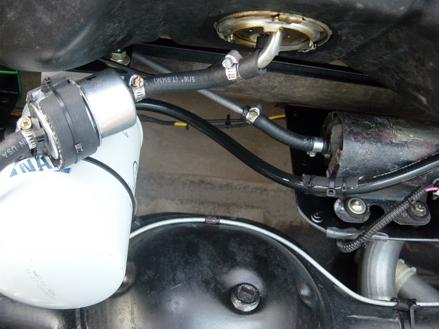
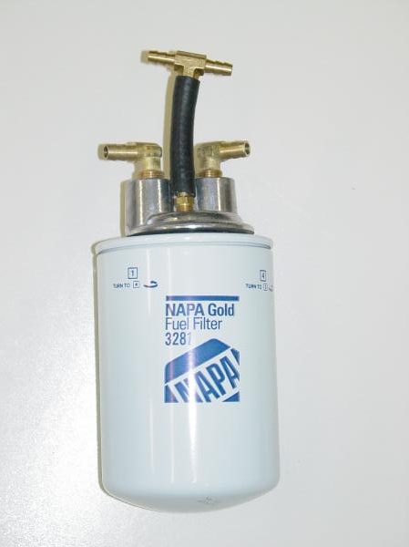
View looking up - filter, LP pump and accumulator. (Click to Enlarge)
 |
 |
 |
 |
 |
 |
| Photo 1 | Photo 2 | Photo 3 | Photo 4 | Photo 5 | Photo 6 |
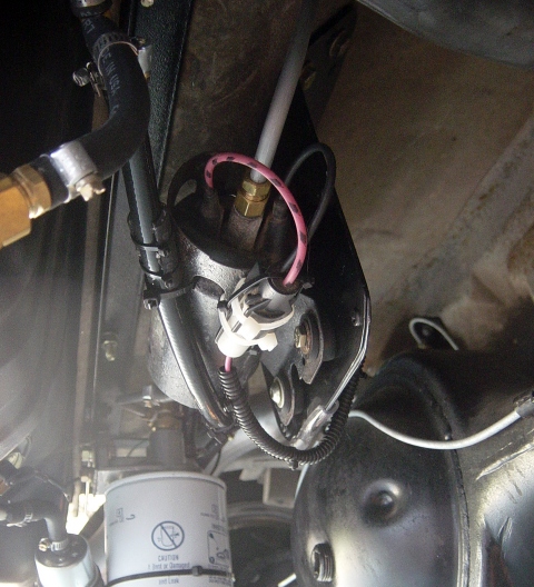
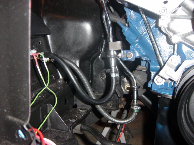
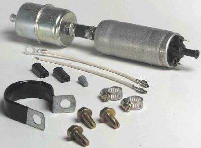
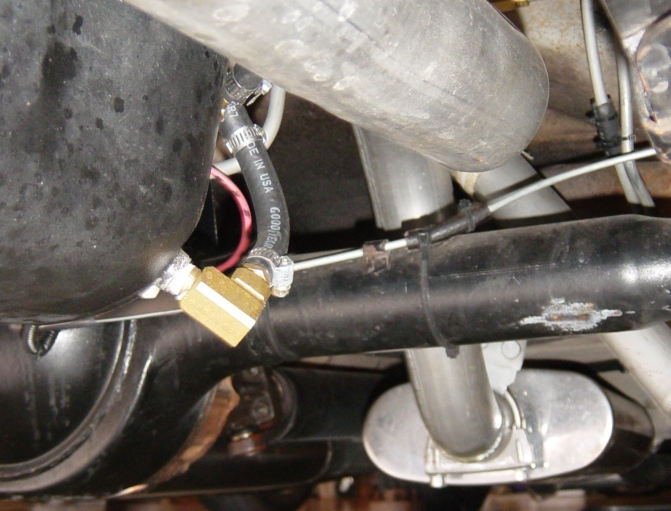
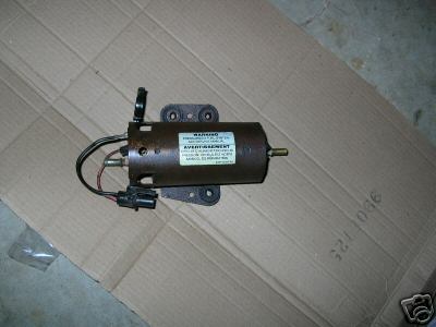
Photo 4 shows the routing/connection between the accumulator tank and the high pressure pump. The HP pump needs to be mounted as close to the accumulator as possible. Photo 5 also shows the HP pump. The bracket to mount the HP pump was home made and modeled after the Ron Morris version, by forming and riveting to pieces if sheet metal into a 1/8" thick assembly. Considering the time it took to make it, it would have been cheaper to buy the Ron Morris unit. The HP pump mounts in a cradle for support and vibration dampening. This is a stock HP external pump from a Ford F150 pickup. I picked this unit up off Ebay (Photo 15) for about 40 bucks.
 |
 |
 |
 |
 |
| Photo 7 | Photo 8 | Photo 9 | Photo 10 | Photo 11 |
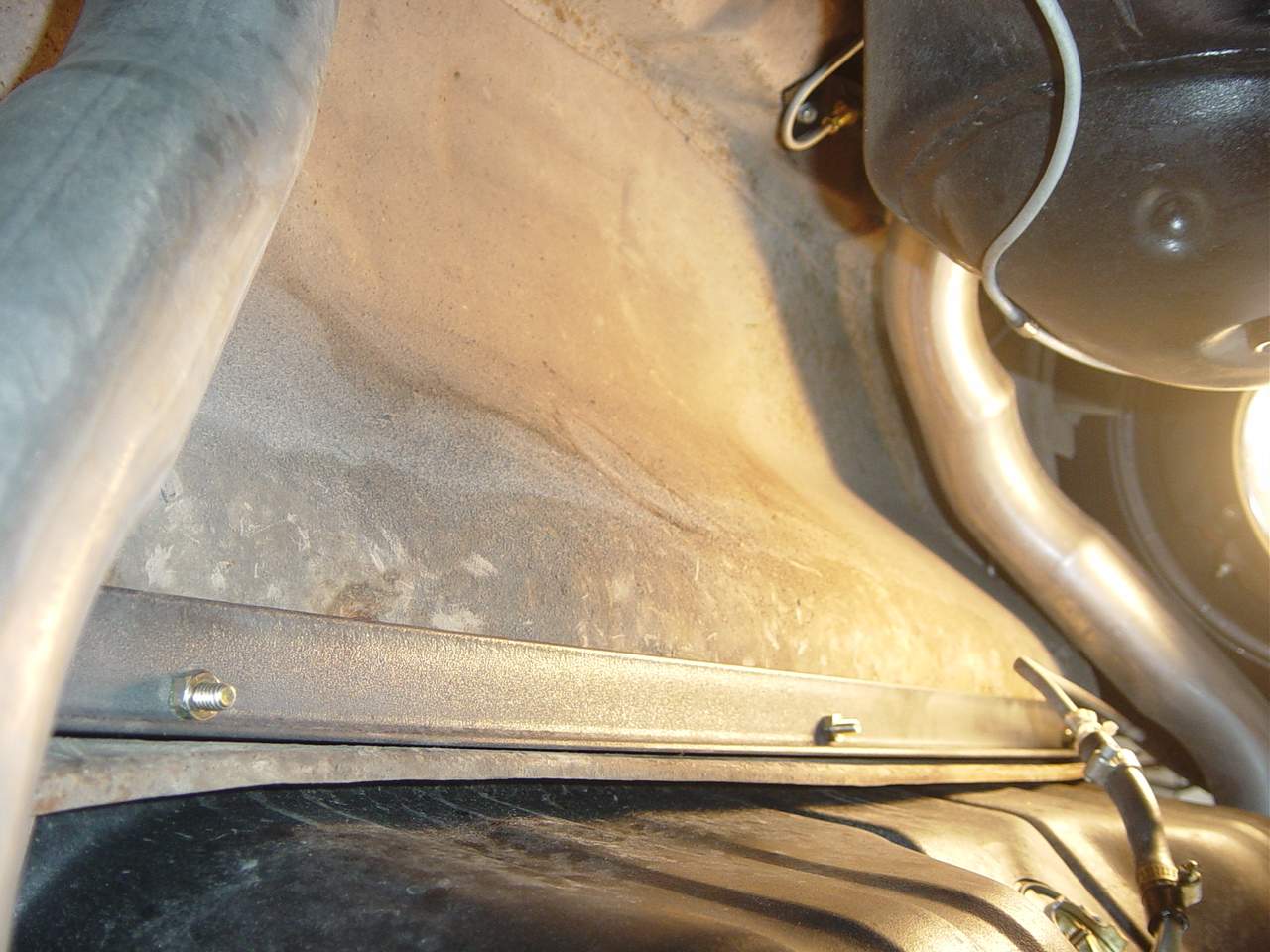
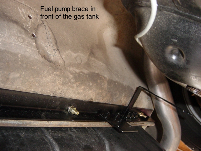
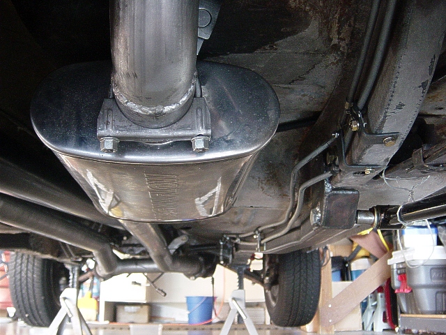
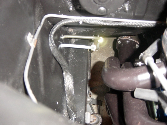
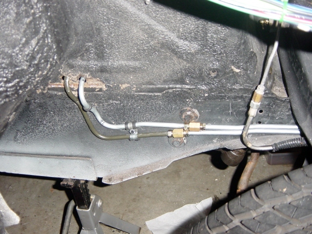
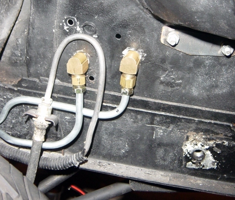
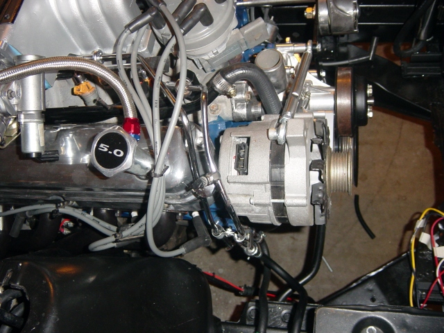
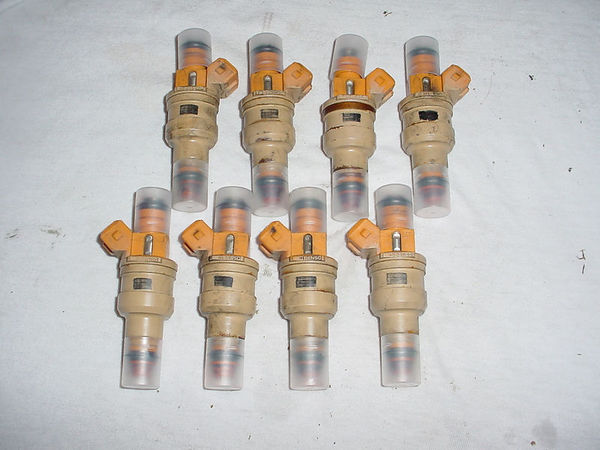
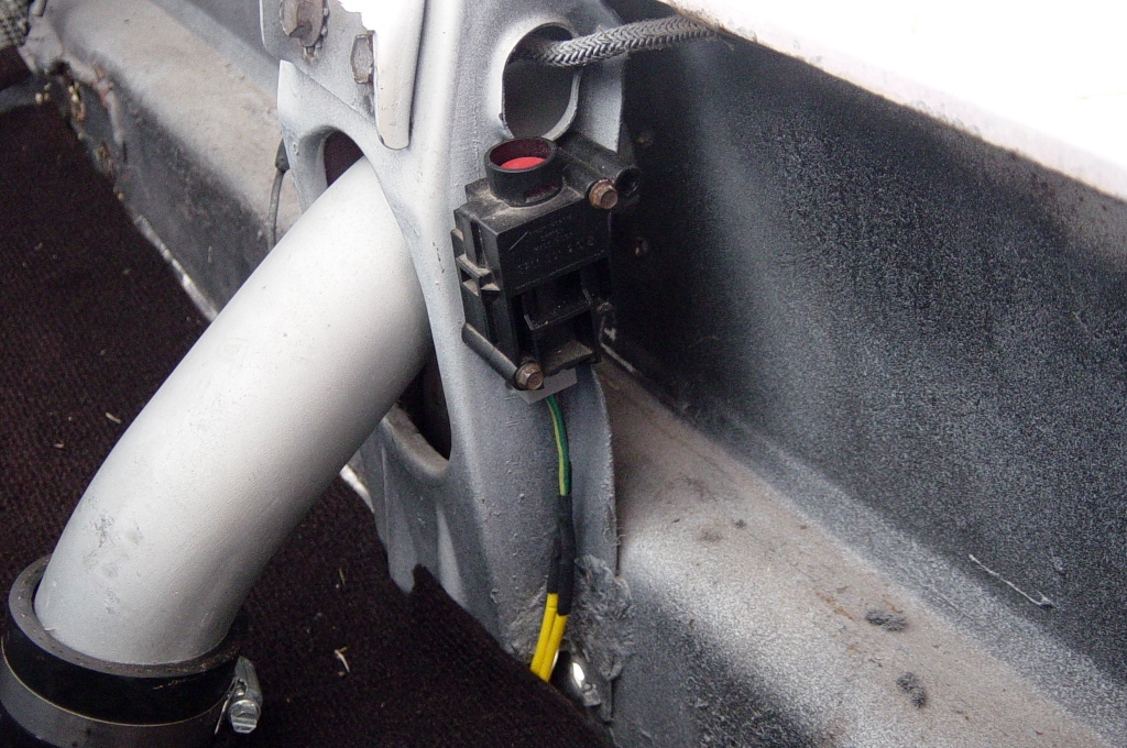
From the HP pump, a steel 5/16" fuel line is run up over along the rear frame rail and up the passenger side of the car, in this case along the subframe connectors. (Photo 6). without subfames, the lines would mount flush against the floor panels and would have to be secured with adels through the floor. The lines run up the inside of the front frame rail then enter the engine bay behind the passenger kickboard (Photo 7). Care must be taken at this location, being the closest point to the exhaust. The lines were secured at approx 18" intervals with clamps/adels. At this point, the lines exit the bay and are run along the outside of the car. The reason for this is that I could find no way to get the fuel lines to the front of the motor without going over the exhaust system. For safety reasons, I did not want the potential for a fuel leak to run onto a hot exhaust and cause a fire. The lines run outside the car and along the frame rail, and turn to re-enter the car below the battery area. (Photos 8 & 9). From here, fittings turn into the engine bay and have rubber hose barbs to attach the flex fuel line. (Photo 10). Throughout this run, there are line breaks in order to make installation easier. For all line connections, brass fittings and double flare connections were used. It is plumbed in the same manner a brake lines. The fuel lines to the motor are stock Mustang 5.0 fuel rails and rail extensions. The OEM lines were re-bent slightly to clear some modifications, and then attach to the rubber lines using the OEM style fittings (Photos 10 & 11). The fuel rails, fittings, fuel pressure regulator, and injectors are stock Mustang units.
|
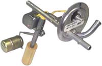
Return line: The 2 steel fuel lines run in parallel through out the system all the way back to the aft frame rail. At that point, the return line is changed to a low pressure rubber line, and it plumbed to tee off and mate with the return port on the accumulator tank. The other end of the tee attaches to the drain port of the fuel tank. Note: I had replaced the tank with a repop tank that was equipped with a drain plug. This made for an easy attachment. (Photo 5). If your tank does not have a drain plug, then the most common alternative is to use a modified fuel sending unit like this one by Ron Morris. |
||||
 |
 |
 |
 |
 |
| Photo 12 | Photo 13 | Photo 14 | Photo 15 | Photo 16 |