Battery Box Relocation - 65-66 Mustang Fastback
- Do nothing, this leaves you with a cramped area to install your breather, and makes for lots of exposed wiring under the hood.
- Turn the battery box sideways (using a 69-70 battery tray), this works better for the air filter but still limits the space and the wiring is still there
- Relocated to the battery to driver's side front apron; this fits the original wiring scheme of the Fox EEC-IV harness. It still leaves all the wiring exposed, and you have to fabricate a new battery box and support structure, as well as relocate the overflow tank.
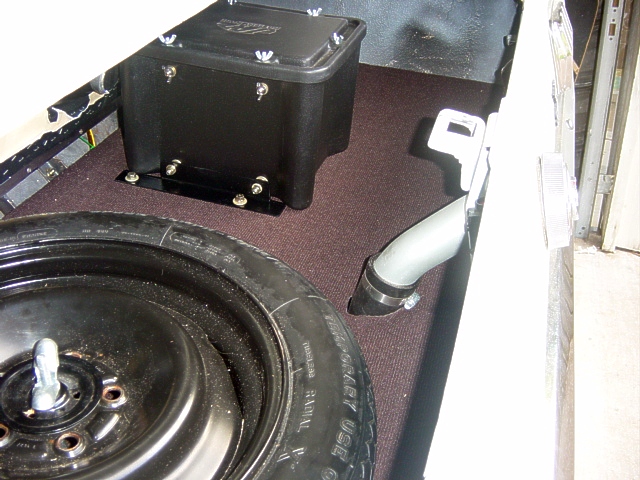
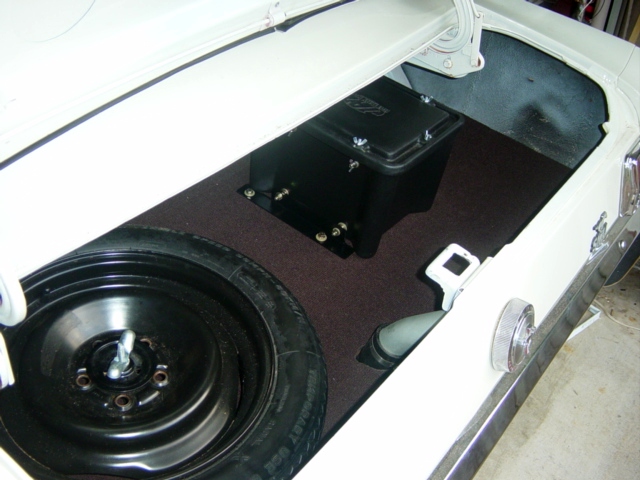
- Relocate the battery to the trunk. This is the most visually appealing and provides the most room for the air filter. The drawbacks are that you have to run extended cables and deal with a battery in the passenger compartment.
As for the latter, there are two choices. You can purchase a sealed battery, such as an Optima, and mount in the truck using standard mounting hardware, or you can use a standard battery with a sealed battery box vented to the outside. For this installation, I chose the latter.
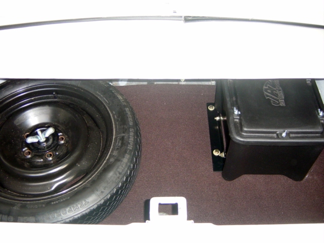
The battery box is secured to the using 1"x1" angle iron as footings. (Photo 5) These are bolted through the plywood, through holes in the angle iron and secured using clipnuts. To remove the battery box, the bolts are removed and the box slid forward. Inside the box, steel straps are mounted up the interior sides of the box and attach to angle brackets which secure the battery inside the box. (Photo 2)
 |
 |
 |
 |
 |
| Photo 1 | Photo 2 | Photo 3 | Photo 4 | Photo 5 |
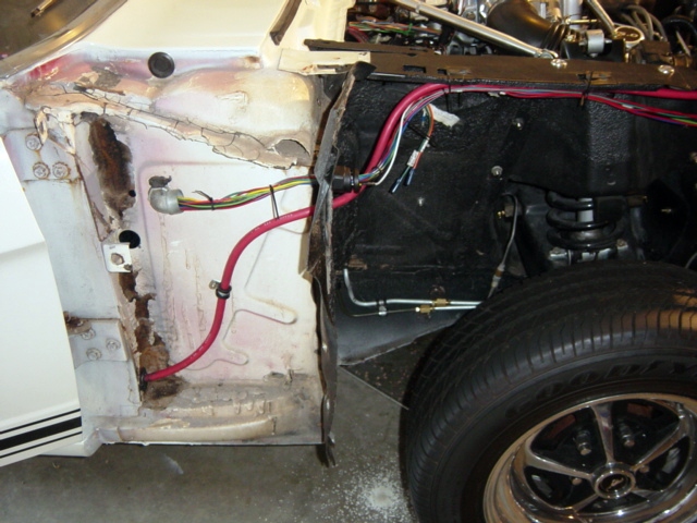
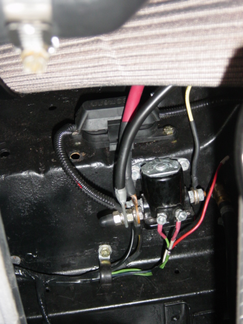
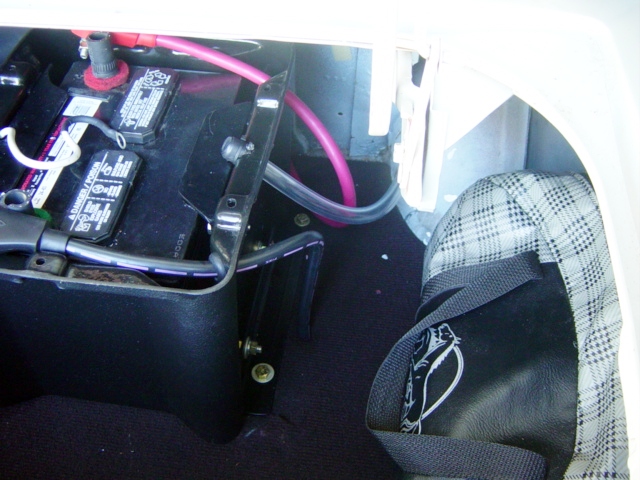
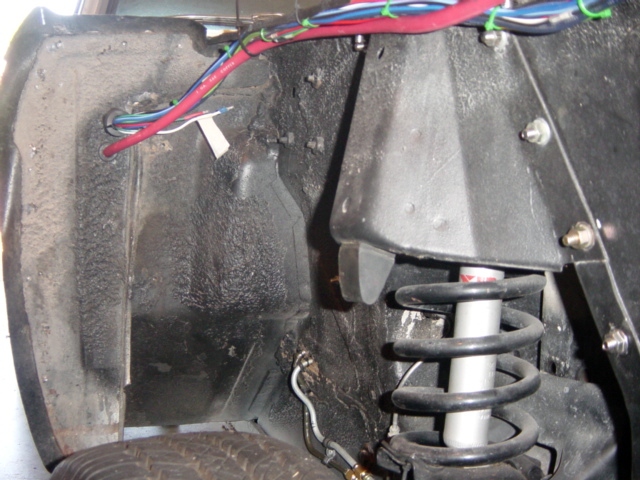
The positive cable runs from the battery box, under the rear seat (Photo 2), through the passenger door well, and into the panel behind the kickboard. From here, a hole is drilled and the cable routed behind the fender up to the splash panel (Photo 3). The cable then runs along the top of the fender apron till it reaches the old battery tray area. (Photo 4), Here, the cable is routed into the engine bay and down to the starter solenoid, which has been relocated down to just above the framerail. (Photo 6). At final installation, this cable run is covered with a large rubber hose that is cut and slides over all wiring protecting it from damage. Rubber grommets secured with silicone adhesive are used in all areas where the cable passes through a panel. Rubber lined adel clamps are used to secure the cable along the run. In any locations where chaffing could occur, insulation is installed (Photo 2). The ends are swaged and soldered to the end of the cable.
The negative cable runs out of the battery box, and down through a rubber grommet in the trunk floor. The end of the cable is soldered and swaged, and secured to the rear frame rail. A clean surface and strong bond is needed to ensure a good vehicle ground.
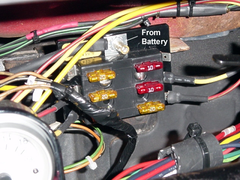
The third wire is optional. I chose to run an independent 8 gage wire from the positive post of the battery along the drivers side and up behind the dash in order to feed the vehicle's main power distribution system. This replaced the original Black/Yellow wire that drew vehicle power from the + post of the starter solenoid. The reason this wire was added was to shorten the total wire length to the main fuse panel, and to avoid any spikes or voltage drops from picking up the power at the solenoid.
 |
 |
|
 |
 |
|
| Photo 1 | Photo 2 | Photo 3 | Photo 4 | Photo 5 | Photo 6 |