|
The
lower mounts were made from 1/8" steel, folded to form a left and
right cradle. The driver's side is shown here, along with how I
drilled two holes and used clipnuts to attach the bracket to the core
support. I experimented with various foam rubber and rubber inserts to
properly space and cushion the side tanks. Notice
the upper retainer is different in this photo than the one above.
The first one was too large and distracting. The bracket shown
to the far left wraps around the tank and secures to the existing upper
radiator bracket hole. No drilling is required. |
  |
|
The upper bracket on
the driver's side is not shown in any of these photos, but is not square
like the pax side. That side of the tank is rounded in it's
transition to the pressure cap. The bracket on that side is round,
and follows the contour of the tank. Another option is to use
3" standoffs and run them from the upper flange of the radiator to
the core support. I've seen this installation and it looks very
clean. |
|
Wiring &
Temperature Sensor: |
|
|
Wiring is standard
setup.... us a relay like those listed on my headlight page.
.
| Run
hot signal from a switched battery source.
|
| Main
power comes from a battery term of the Solenoid.
|
| Main
power out to the fan..
|
| Ground
Lead from Fan to Chassis Ground |
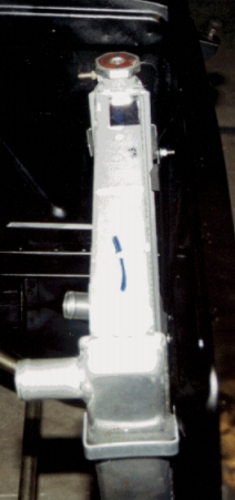
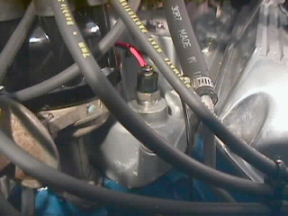
| Relay
Signal ground to the Temp sensor, shown here. Shown is a Spal
brand temp sensor. It will turn the fan off/on by reaching
185 temperature and grounding the circuit, turning on the fan.
I almost immediately broke this temp sensor, cracking the top stud
out of the phenolic housing. After that, I went down to AutoZone
and asked for PN SW649. It's a factory version of the same
item and costs about half as much. |
|
|
SPAL Fan
Installation: |
|
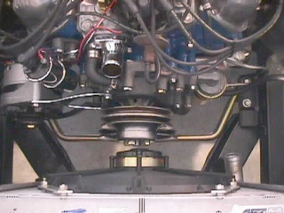
How's
this for clearance. There's all of maybe 3/8" between the fan
and the pulley bolt heads. But a miss is as good as a
mile.
The
fan is a SPAL, 16" puller, rated at 2360 CFM. I chose it
because of it's good reviews, 3.7" depth, and availability on EBAY
for 2/3's the price of retail. Be
prepared tho...this fan has a startup draw of over 25 amps. You need
to have a stout alternator. |
 |
|
Battery Tray
Relocation: |
|
|
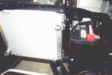
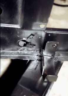
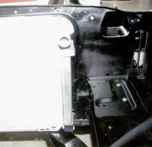
Although not
necessary to install the new tank, changing over to a 69-70 battery tray
provides a lot more room to work.
To install the
tray, the lower leg must be cut and re-bent to allow the tray to sit flush
on the apron shelf. The apron must be 'percussion engineered' as MS
puts it, to allow for the tray to fit outboard as far as possible. I
took the middle approach, and beat the apron to the point that I felt it
could actually tear, and then cut the corner of the tray to clear the
interference. Not the notch in the lower right of the tray in the photo
below.
To reinforce the
mounting, I also installed an 6" long angle brace on the underside of
the shelf. |
|
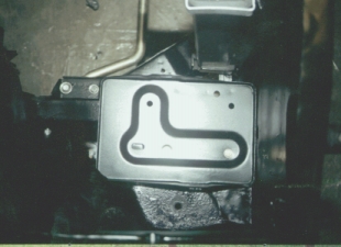
Looking
straight down on the relocated battery tray. The outboard edge of the tray
lines up with the top of the fender apron. A small pocket still
remains (Thinking about making a block off plate out of sheet metal and
hiding the starter solenoid there.) When
purchasing the 69-70 tray, you will also need the two tie-down posts and
the battery cross brace. Questions?
Email me. |
 |
|
20 August 2002 |