|
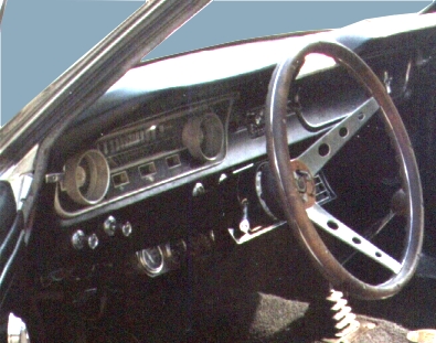
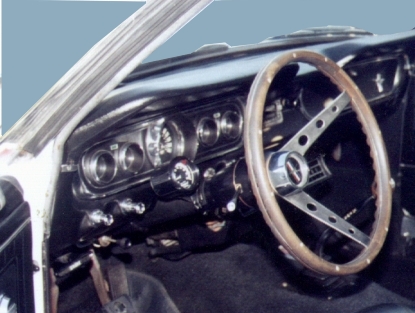
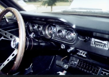
Changing the 65 Idiot Light Dash to the 66 Guage Dash |
||||||||||||||||||||||||||||||||||||||||||||||||||||||||||||||||||||||||||||||||||||
|
||||||||||||||||||||||||||||||||||||||||||||||||||||||||||||||||||||||||||||||||||||
|
Not as complicated as you may think..... NOTE: This web page is meant to describe what it takes to convert the wiring of an existing 65 with indicator lights over to a 66 configuration with the 5 gage cluster. It is NOT as simple as just changing out the instrument panel. If you opt not to change over the charging circuitry, but would rather leave the ALT lamp and just stick it behind the dash or something... then by all means have at it, as it is your car and your memory of the wiring status. There is probably some other web page that explains how to do that method, but it is not addressed here. I personally believe the best approach is to accurately rewire the engine compartment completely to the 66 configuration. Shopping list: - Books: First, go and buy the Jim Osborn Wiring Diagram Manuals for both the 1965 and 1966. They are invaluable for working on these cars. You'll basically be comparing the wiring between the two and converting from the 65's to the 66's. Also, the "Mustang How-To, Vol.1" book's article on "How to Convert 1964 1/2-65 Mustang Idiot Lights to Gauges" is where I learned to do this. Here are the things you'll need to make the swap. That, and a few hours......
The 'new' dash unit - '66 gauge clusters used to be a dime a dozen at the swap meets. They were the bait that the vendor uses to tell you what kind of car he's parted out and is selling. They can run anywhere from five to fifty bucks for the exact same unit. They are getting increasingly harder to find. EBAY regularly has them posted and typically go for between 20 and 40 depending on condition. So shop around. Look them over closely. Forget about the front bezel and the lenses because you're going to replace them anyway. You're after the internals and the back housing. Make sure the units are relatively clean, straight, not been sitting out exposed to the weather. Housings with rust on the back are typically not a good sign. You can find one out there that's not rusty.
The night after you get it...go ahead and annoy your wife by taking over the kitchen table as your work table, to disassemble your new/old 66 gauge unit. Inspect it carefully for broken wires or other damage. Handle the gauges carefully because, for example, the Ammeter gauge is $80 to replace. (Been there, done that....) Clean the gauge face of the unit with a soft damp rag. Put paper under the needles and touch them up with the bright orange florescent paint. Reassemble using the new lenses and bezel. If you're going to install white faces, now's the time. Water Temperature - This shouldn't be much of a change, unless yours was like mine and years of previous modifications had crept in...I had the Pep Boy's Special 'Triple Gage Cluster'...installed under the dash. So, I had to recreate the original setup.
Oil Pressure - Not identical. The 65 has an oil pressure sending unit made for the OIL light, which is different than the one for the 66 gages.
Gas Gage - The Gas Gage on the 65 is the same hook up as on the 66. The Yellow-white wire from the tank goes to the speedo side post, while the other side of the gage runs to the CVU.
The gas, oil, and temp all have one side that is tied to the CVU. The other side goes to the appropriate sensor, and the variance in ground by the sensor makes the needle move. I made a separate little harness, running from the CVU to the three gages and hanging it on the back of the gage pack. Connect the black-green wire from the main loom to the straight up & down post of the CVU. Turn Signals - Slight mod required, as the 65 has one lamp for both left and right. The 66 has separate lamps for left and right. Take the turn signal lamp socket currently in the existing 65 harness and cut out the existing socket. Then, splice in the single wire lamp socket you found at the swap meet to each of the cut leads. The left turn is the Green-White wire, while the right is the White-Blue. Where do you get these single wire light sockets? (These are the ones that have the little metal teeth around the socket that holds it in place in the metal dash housing....also grounding the lamp and completing circuit. I got mine at the swap meet... I picked up a ragged old wiring harness out of some old GM product and the guy was trying to pay me to take it...but I insisted on paying him $1 for the harness. I was able to salvage off a few connectors and the required lamp sockets.) Lighting - Guess what.... the dash is going to be dim...even after you clean out the little blue green bulb lenses, put in brand new bulbs, and make perfectly soldered and fully grounded wiring connections. But if you DON'T do all those things, they will be even DIMMER. So polish out the little bulb lenses, put in all new bulbs, and make perfectly soldered and fully grounded wiring connections. This is where those bright orange needles you touched up come into play. There are 4 lamp sockets. Make sure they all work before you put the thing back together and screw in the dash. MustangSteve offers up two additional suggestions: 1) add a couple of lights to the assembly by drilling holes in the back of the gage housing at symmetric points and wiring in two new sockets, and 2) simply removing the blue-green lenses. Both of these increased the lighting with no additional glare. Good advice Steve. High Beam Indicator - no biggie...plug the lamp with the NEW BULB into the center socket in the new dash. Ammeter (not voltmeter) - The Ammeter us just that...it measures the amperage flow (duh). It's sort of a bridge between the alternator and the battery to show you if the system if charging, or drawing current. This is not the same as a modern voltmeter, which tells you the output value of the alternator. Disclaimer - If all you intend to do is replace the gage cluster but leave the charging circuitry for the 65 intact, then stop here. Leave the ALT lamp wired in and hide it somewhere (preferably some place that you have a chance of seeing if you ever develop charging issues. Behind the heater controls has been suggested before.) If you decide to simply hook the Ammeter to the Alternator and the Battery and not adjust the rest of the wiring, I have no idea how that will work. However, if you intend to actually complete the rewiring of the 65 into a 66 configuration, then read on: Here, you're doing away with the 65's charge indicator light circuit, and running new red/yellow wires from the back of the gage pack to the + post on the starter relay (red wire) and to the large lug (BAT) of the alternator (yellow). Note: This yellow connection serves as more than just a pure gage lead. It moves the 654 pigtail connection to the BAT post of the alternator. On the gage pack, be sure that the red goes to the speedometer side term, and the yellow goes to the radio side.
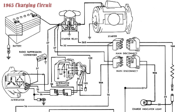
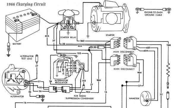
I had some trouble following the "How To" article on this part...basically after I got through, the alternator wasn't charging the battery...soooo...I finally figured out that the article left out one small detail about the hook up of the voltage regulator..... The 65 has a white-black wire running from the common post of the Alternator to the Voltage regulator. This wire is not on the 66 schematic. You have to remove it and splice in the Green Red. Hopefully these schematics below will also help in understanding the difference:
Other General Info/hints:
Ok...there you have it. I wish I'd taken pics when I did this mod last year. Maybe the next time I have the dash out, I'll take some and add them to the page. If you have any questions, email me.
|
||||||||||||||||||||||||||||||||||||||||||||||||||||||||||||||||||||||||||||||||||||