Wiring a Fuel Injected 5.0 into a '65 Mustang
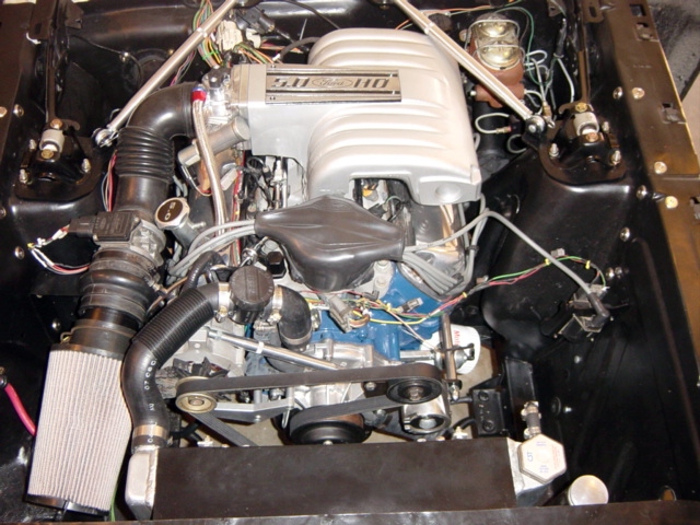
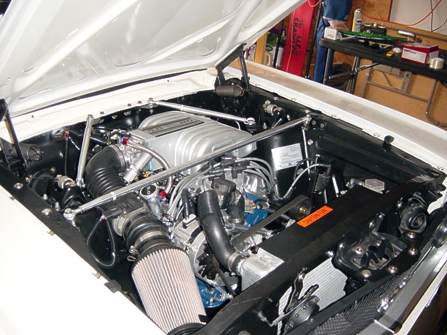
The purpose of this page is to describe the wiring modifications necessary to install a 87-93 SEFI 5.0 into an early model Mustang. These are the steps I went through to run the motor shown to the right. Your install may vary....
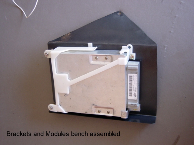
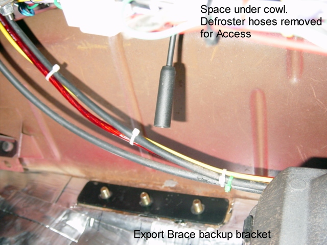
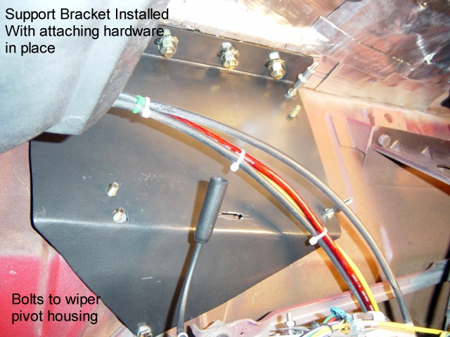
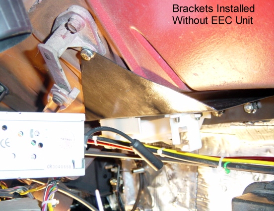
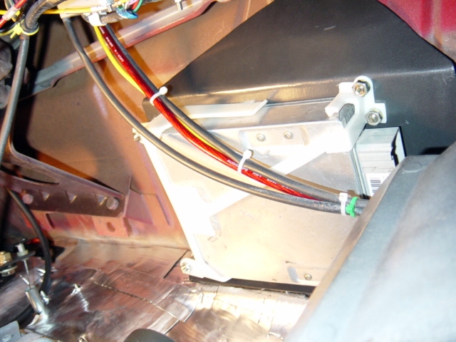
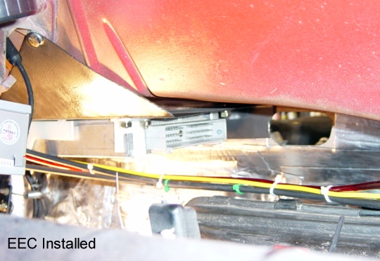
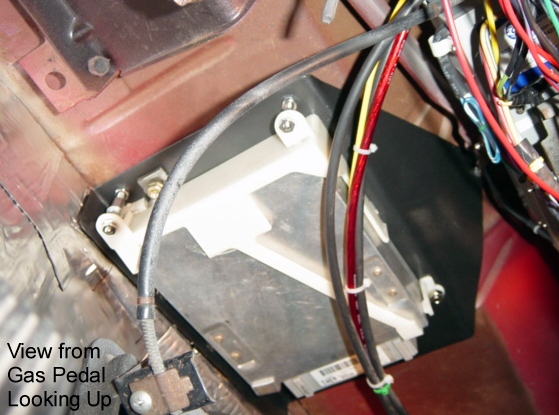
Computer Install: Location of the computer is critical to determine wire routing. There are several options for location, such as along the pass kick panel and behind the Glove box. Location will be determined by the availability of space. I chose to mount the computer below the cowl and above/behind the radio, as shown below right: The mounting bracket secures to the front firewall, and extends up behind the cowl to attach to the wiper pivot bracket. This location provided the best clearance. The following photos detail the installation:
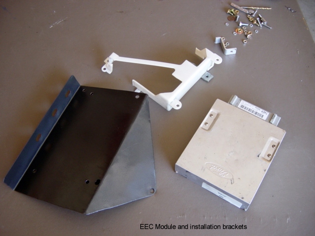
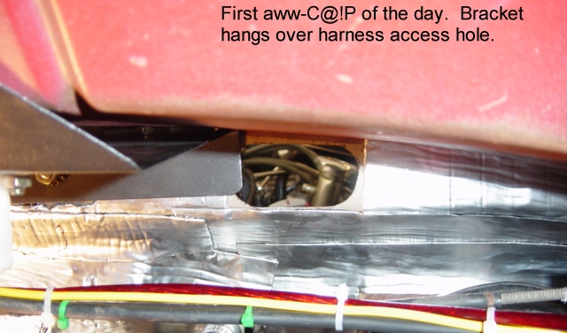
Assembly of bracketry: Bracket was formed up from 18 gage sheet stock using this PDF File; graciously designed and passed forward by Jason5.0. EEC mount was salvage from wrecking yard. Fasteners from local hardware store:
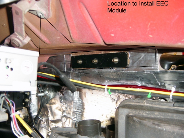
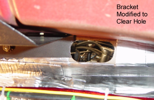
Locating Computer: The follow photos depict the location of the bracket installed, and the location of the firewall feed thru hole for the main EFI loom. This location clears the defroster ducts as well as all existing wiring. It also leaves space for installation of the various relays and MAP sensor.
Check out Jeff Gordon's version of the same concept. (Pages 2 & 3 on his site) This is VERY well done. Excellant idea to lower the bracket and use the top to mount components.
EFI Wiring Harness: There are several options regarding wiring your EFI computer to your new 5.0 setup. These include numerous ready made harnesses on the market. Ford Motorsports, Ron Francis, EZ Wiring, FordFuelInjection, Windsor-Fox, Ron Morris, and Painless are just a few of the names that come to mind. Each of these are top quality and provide a much simpler method of connecting your wiring.
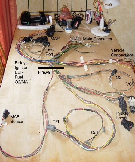
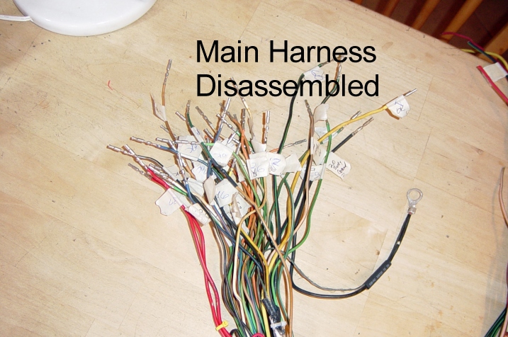
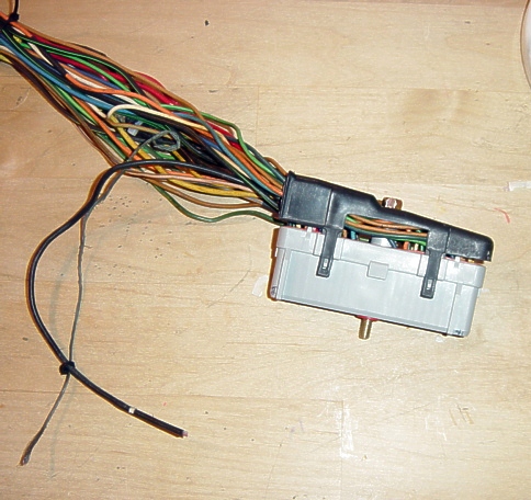
For me, I felt that the best way to know my car and my system was to touch every wire and understand it's function. I felt I would have a better chance of troubleshooting if I understood the wiring completely. Also, I prefer to take the lowest cost (but often the most labor intensive) route. So, to that end, I chose to take a factory harness from an 89-93 Mustang and modify. The photo to the right shows the complete harness disassembled and rerouted to it's final configuration. This is the way my harness looked as installed in the car.
Harness Modification: To modify an existing harness, get one that is complete and unmolested. It should include:
-
Main loom,
-
O2 loom (a Y shaped cable that connects the 2 O2 sensors to the main loom),
-
Injector loom (the small harness that connects the injectors and sensors to the main loom through the large black and white connectors.)
-
VSS Cable (connects the VSS plug of the main loom to the VSS sensor on the speedometer cable)
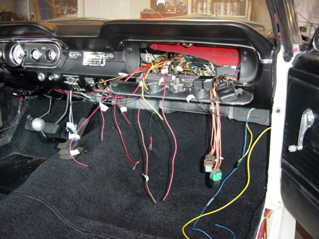
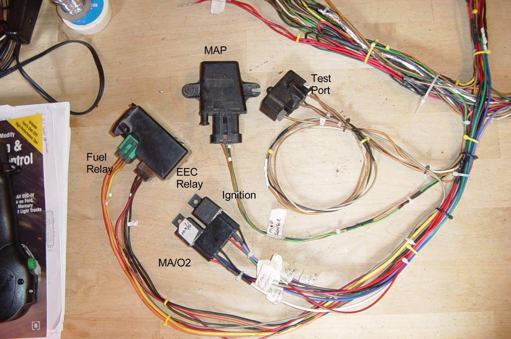
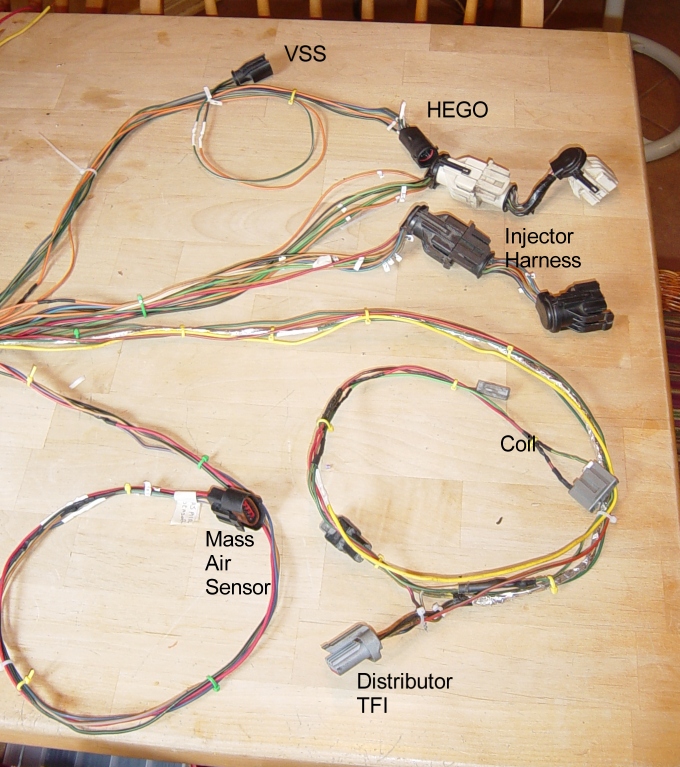
I chose to hide as much of the wiring as possible under the dash and leave only the necessary wiring in the engine compartment. This meant changing the lengths and routing of essentially every wire. Note: all connections/cuts/splices must be properly joined, soldered and sleeved with a proper fitting heat shrink sleeving. The EEC system is very sensitive and crimped connections can cause all kinds of problems down stream. There were only 7 connectors (MAF, TFI, Coil, Black & White connectors, VSS and O2) that ended up in the engine bay; everything else was rerouted to under dash.
The original harness was completely unwrapped; all coverings and tape were removed. Each wire was cleaned using a rag and ordinary hand cleaner (GoJo). Each wire was inspected for cracks, frays, nicks, burns, or any other damage. Each connector was inspected for cracks, burns, dirt, or wear and replaced if needed. Taking the time to fix now will save time later. Use zip or twist ties to temp route your wires.
The Ford Fuel Injection, and Detailed Wiring Diagrams links shown to the right covered most everything needed in order to understand and rework the harness. Study these two websites in detail to see how the harness and sensors work. Page 6 specifically can be used as a guide to harness rework. I copied the wiring table to a spreadsheet and made a checksheet so I could verify each wire correctly. Use this list of wires (and it's preceeding schematic) in conjunction with the pin out shown on the first and second diagrams on the VeryUseful site to get see the total scope of the affected wires.
Also, pay attention to the Harness Ignition Circuit, as there are wires which are not on the table but must be run in conjuction with the harness layout. These include the Tach lead, Coil Leads, and 12V start and run circuits.
Lay the harness out on a large work surface so you can route the wires as needed. Using the table listing of the harness, trace each wire to it's intended location. The 10 pin connector table located at the bottom of Page 6 will aid in tracing wires going into the injector loom. In several cases you may choose to cut and reroute the wire to place the sensor, relay, or plug in a different location. In particular, you will be changing the lengths and locations of connections because much of the loom was routed to the front left side of the engine bay (battery location of a Fox Mustang), and you are relocating to either right side or under dash. Work through the sensor, injectors, and gage wiring first, leaving the power and ground wires for last.
Pay particular attention to the EFI Power diagram midway on Page 6 of the FFI site. Using this diagram allows you do establish a power distribution which reduces the number of power connections to the rest of the vehicle. This diagram adds 2 relays to the removed harness (MA/O2, and Ignition). The 4 relays, along with the MAF and test port can be relocated under the dash, reducing clutter under the hood.
-
It is not necessary to disassemble the main 60 pin connector to perform this mod. The connector I had was cracked so I chose to disassemble and replace. FFI sells all the replacement connectors for this harness.
-
If you are running a T-5, so leave Pins 3&6 for the VSS. You'll need to get a VSS from a local autoparts store, and modify your speedo cable, or.... you can get a modified speedo cable from Ron Morris.
-
Do you have A/C? If so, then you'll need to leave your WOT cut out wire switch and hook it up. If not, then you can remove all associated wiring.
-
You can omit the TAB, TAD, and CANP wires from the harness. (Pins 31, 32, and 38 aren't even shown on the FFI diagram.) You most likely won't be running the smog system. The computer will throw error codes for this but that's ok. Or, you can leave the wires and install resistors in line to trick the computer using resistors.
-
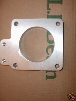
You'll need to leave all the wiring to the EGR, but fool it into thinking it's hooked up. FordFuelInjection sells a $20 plug that terminates this connector, or you can wire in the resistors yourself if you're so inclined. I removed my EGR spacer completely and plugged the coolant lines. Then I installed a billet spacer bought off Ebay.Gives you more space to run your MAF tubing.
-
I did not hook up the NSS... so far I haven't started it in gear and put it through the garage wall...yet.
-
There's a Low Oil wiring that runs along with the O2 harness. This can be removed.
-
In many cases you will be running new wires. Try to use the original wire to the greatest extent possible, as it has the proper color coding. If you have to splice in new wires, they must be marked for future reference. I used adhesive backed lables, marked the EEC connector pin number, and then covered in clear heat shrink. Mark approximately every 10".
-
Start/Run - Between Key switch and Pink resistor wire.
-
Start Only - Starter solenoid rear terminal (S)
-
Run Only - Stud on back of key switch.
Informational Sources:
Connector Layouts
Harness in and out Pinouts
EEC IV and Fusebox Connections

Harness Installation: Carefully feed the harness through the cutout in the firewall. I fed the harness from under dash outward, as this was the smallest amount of wires to move. The wires were laid over the motor to determine approximate locations.
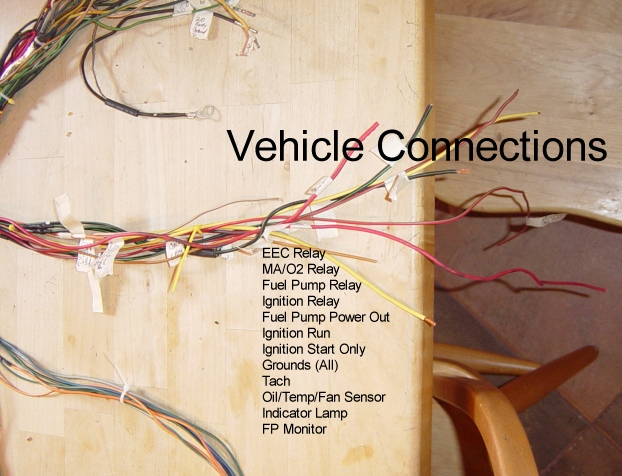
There were 14 under dash connections that needed to be fed from scratch or spliced into the main vehicle underdash harness. These were:
-
4 Relays (EEC, Ignition, Fuel Pump, and MA/O2) to the fusebox or battery power source.
-
5 Gages/Sensors (Oil, Temp, Electric Fan, Tach, & Check Engine light)
-
2 Fuel Pump (1 Power out to FP, 1 FP Monitor)
-
Grounds (all to one ground point)
-
1 - Ignition Run
-
1 - Ignition Start Only
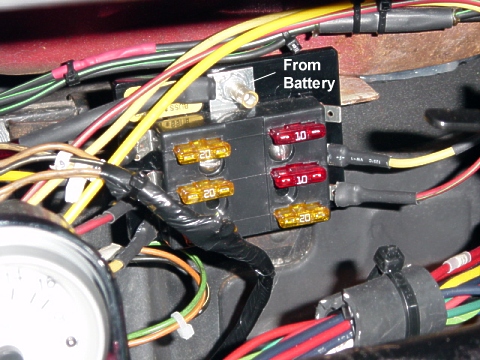
Not necessarily required, but I chose to install a secondary fuel panel to route all EFI Power. This panel is fed directly off the battery positive.
After each wire is connected, the car was started and tested. After the electrical functions have been verified, the harness lengths were adjusted by routing and cutting out excess wire lengths. The harness can then be wrapped or covered with harness sheathing, and stowed as desired.